I work with industrial infrastructure that requires nanosecond-accurate time synchronization. The commercial GPS-disciplined PTP grandmaster clocks that solve this problem run from several thousand dollars on the low end, and considerably more with options and support. I had CM4s and CM4 IO boards already sitting in the lab. A TimeHAT with an OCP M.2 GNSS module would have been the cleaner path at around $400, but that is steep when the goal is learning how PTP actually works, not deploying production infrastructure. This build came in at around $103 in new parts.
This post documents what I built, what broke, what I had to fix, and the results I measured.
What is PTP and why does it matter
Time precision is a spectrum:
| Unit | What it is | Example Uses |
|---|---|---|
| 1 second (s) | The tick of a clock | Human scheduling, cron jobs |
| 1 millisecond (ms) | 1 second split into 1,000 pieces | Web browsing, video streaming, log timestamps |
| 1 microsecond (µs) | 1 second split into 1,000,000 pieces | High-frequency trading, audio/video sync, distributed databases |
| 1 nanosecond (ns) | 1 second split into 1,000,000,000 pieces | Aerospace instrumentation, industrial automation, scientific data acquisition, this build |
NTP is good enough for web servers, databases, authentication systems, and anything where you need to know when something happened but don’t need to coordinate hardware events across machines. Over a LAN with a good reference, NTP can reach low microseconds. Over the WAN it typically lands in the low milliseconds. The ceiling is the network path jitter between client and server, every variable delay adds noise to the offset estimate.
PTP (Precision Time Protocol, IEEE 1588) handles the nanosecond tier. With hardware timestamping at the Ethernet PHY layer, PTP can synchronize clocks to within tens of nanoseconds on a local network. The grandmaster clock is the root time source. It takes GPS-disciplined time and distributes it to clients via the PTP protocol.
A nanosecond is the time it takes light to travel about 30 centimeters (roughly 1 foot). After this build, the clocks on my homelab nodes were off from GPS truth by the time it takes light to travel across a room.
Hardware
| Component | Notes | Cost |
|---|---|---|
| Raspberry Pi CM4 (8GB/32GB eMMC) | Already owned | N/A |
| CM4 IO Board | Already owned | N/A |
| SR1723U10 GPS module | u-blox M10 based | ~$15 |
| JEFA Tech U.FL to SMA pigtail | For antenna connection | ~$8 |
| Bingfu GPS antenna | Active, SMA | ~$12 |
| MOOKEERF SMA cables | Various lengths | ~$10 |
| Waveshare CM4 IO Board case | 1U aluminum | ~$25 |
| ELEGOO Dupont jumper wire kit | For wiring | ~$8 |
| M2.5 standoff kit | Mounting hardware | ~$8 |
| 12V 2A power supply | For IO board | ~$12 |
| CR2032 battery | For onboard RTC | ~$5 |
| Total (new parts) | ~$103 |
The CM4 and IO board were already on hand.
This build vs the TimeHAT path:
| This Build | TimeHAT Path | |
|---|---|---|
| Compute | CM4 + IO Board (owned) | Raspberry Pi 5 (~$80) |
| GPS integration | SR1723U10 + wiring (~$23) | TimeHAT + OCP M.2 GNSS module (~$395) |
| Antenna | Bingfu + pigtail (~$20) | Same antenna works (~$20) |
| Oscillator | Standard crystal | TCXO (temperature compensated) |
| New spend | ~$103 | ~$475+ |
The oscillator difference matters. The TimeHAT includes a TCXO, which compensates for temperature-induced frequency drift. During GPS holdover, a TCXO holds time significantly more accurately than a standard crystal because its frequency stays stable as the board heats up or cools down. The CM4 uses a standard crystal with no temperature compensation. This build held 15ms of drift over 10 hours of holdover, which was acceptable for this use case. In a production environment where holdover accuracy is critical, the TCXO is worth the cost difference.
The TimeHAT also uses an Intel i226 NIC rather than relying on the CM4’s onboard BCM54210PE, uses proper SMA connectors, and requires no jumper wires. If you are starting from zero hardware, that path is easier. If you have a CM4 already and want to understand what is happening at the PHY level, this build gets you there for a fraction of the cost.
The key hardware fact: The CM4 uses the BCM54210PE Ethernet PHY which has full IEEE 1588v2 hardware timestamping support. This is what makes sub-microsecond PTP possible on the CM4. The BCM54210PE timestamps packets right at the wire inside the PHY, before the packet touches the kernel network stack. This eliminates the jitter that comes from kernel scheduling and interrupt handling.
Clients:
- Turing Pi 2 cluster board (RTL8370MB-CG+ switch)
- RK1 compute module (Rockchip RK3588, Ubuntu 22.04)
- CM4 (Ubuntu 24.04), the k8s1 node
The Turing Pi 2 has two external RJ45 ports. Both ports are bridged into the same switch fabric as the four node slots. The grandmaster is plugged into ge1 (the second RJ45 port). The RK1 and CM4 client nodes are on the internal node slots. All five are on the same RTL8370MB-CG+ switch fabric, which means PTP packets between the grandmaster and clients pass through a single switch hop with no routing involved.
Why Ubuntu 24.04
The CM4 was originally running Ubuntu 22.04 with kernel 5.15.0-1093-raspi. The BCM54210PE PTP support was added to the Raspberry Pi kernel tree in 2022 and subsequently upstreamed to mainline Linux, but Ubuntu 22.04’s raspi kernel did not include it. The result was no PHC device and no hardware timestamping:
$ ethtool -T eth0
Time stamping parameters for eth0:
  Capabilities:
    software-transmit
    software-receive
    software-system-clock
  PTP Hardware Clock: none

$ ls /sys/class/ptp/
(empty)
Without /dev/ptp0, SatPulse has no hardware clock to discipline. There is no path from GPS to network time.
There was also a secondary issue: Ubuntu 22.04 had console=ttyAMA0,115200 in cmdline.txt, attaching the kernel console to the same UART the GPS module uses. This caused continuous input overruns in dmesg and garbage output from the GPS port.
Upgrading to Ubuntu 24.04 with kernel 6.8.0-raspi fixed both problems:
$ ethtool -T eth0
Time stamping parameters for eth0:
  Capabilities:
    hardware-transmit
    hardware-receive
    hardware-raw-clock
  PTP Hardware Clock: 0

$ ls /sys/class/ptp/
ptp0
Wiring
The SR1723U10 connects to the CM4 IO Board via five Dupont wires. Four carry power and serial UART. The fifth carries the PPS signal to the J2 header.
| SR1723U10 pin | Color | CM4 IO Board |
|---|---|---|
| VCC | Red | 40-pin pin 1 (3.3V) |
| GND | Brown | 40-pin pin 6 |
| TX | Orange | 40-pin pin 10 (RXD0) |
| RX | Yellow | 40-pin pin 8 (TXD0) |
| PPS | Green | J2 header pin 9 (SYNC_OUT) |
The J2 header is the small 10-pin header on the CM4 IO Board near the Ethernet jack. Pin 9 is labeled SYNC_OUT and connects to the BCM54210PE PHY’s external timestamp input. This is how the GPS pulse-per-second signal gets into the hardware clock.
OS setup
Add to /boot/firmware/config.txt:
dtoverlay=disable-bt
enable_uart=1
dtoverlay=i2c-rtc,pcf85063a,i2c_csi_dsi
The first two lines disable Bluetooth and connect /dev/ttyAMA0 to the GPIO header so the GPS module can communicate with the CM4. The third line enables the onboard PCF85063A real-time clock on the correct I2C bus for the CM4 IO Board.
Remove the serial console from /boot/firmware/cmdline.txt:
# Remove this portion from cmdline.txt:
console=ttyAMA0,115200
Disable the Bluetooth service. The dtoverlay=disable-bt overlay disconnects Bluetooth from the UART hardware, but the hciuart service will still try to initialize and may interfere:
sudo systemctl disable hciuart
After reboot verify the GPS module is outputting NMEA at 38400 baud:
(stty 38400 -echo -icrnl; cat) </dev/ttyAMA0 | head -10
You should see lines starting with $GNRMC, $GNGGA, and similar. The SR1723U10 defaults to 38400 baud, not the 9600 that many guides assume.
Software stack
The stack is SatPulse + ptp4l + chrony. SatPulse is a daemon written by jclark that ties the GPS module, the PHC, ptp4l, and chrony together. It handles GPS configuration via UBX protocol, reads PPS timestamps from the PHC, disciplines the PHC frequency, and feeds samples to chrony via a SOCK refclock.
Install SatPulse from the GitHub releases page (arm64 .deb):
wget https://github.com/jclark/satpulse/releases/download/v0.3.0/satpulse_0.3.0_arm64.deb
sudo dpkg -i satpulse_0.3.0_arm64.deb
Configure SatPulse at /etc/satpulse.toml:
[phc]
interface = "eth0"

[serial]
speed = 38400

[gps]
config = true

[ntp]
sock.path = "/var/run/chrony.satpulse.sock"

[ptp]
ptp4l.udsAddress = "/var/run/ptp4l"
Install linuxptp and configure ptp4l as grandmaster at /etc/linuxptp/ptp4l.conf:
[global]
masterOnly 1
tx_timestamp_timeout 100
ptp_minor_version 0

[eth0]
Copy the SatPulse ptp4l service file:
sudo cp /usr/share/doc/satpulse/ptp4l.service /etc/systemd/system/ptp4l.service
sudo systemctl daemon-reload
sudo systemctl enable --now ptp4l
Configure chrony at /etc/chrony/conf.d/satpulse.conf:
refclock SOCK /var/run/chrony.satpulse.sock poll 2 filter 4 refid GNSS
Add an allow directive to /etc/chrony/chrony.conf so clients can use the grandmaster as an NTP server:
allow 192.168.0.0/24
log tracking measurements statistics
Restart chrony:
sudo systemctl restart chrony
Enable and start SatPulse:
sudo systemctl enable --now satpulse@ttyAMA0
Bugs and gotchas
This is where it got interesting.
The BCM54210PE SYNC_OUT pin bug
Every time the system boots, the BCM54210PE driver initializes the SYNC_OUT pin as output (1 0) instead of input (0 1). SatPulse tries to reconfigure it but fails silently. The result is no PTP hardware clock external timestamps being received and a completely non-functional grandmaster.
Diagnose it:
cat /sys/class/ptp/ptp0/pins/SYNC_OUT
# "1 0" means the pin is stuck in output mode

sudo satpulsetool sdp -i --pin 0 eth0
# "no timestamps received" means the PHC is not getting PPS
Fix it by forcing the pin into the correct state before SatPulse starts. Create /etc/systemd/system/satpulse@.service.d/override.conf:
[Unit]
After=chrony.service ptp4l.service
Requires=chrony.service

[Service]
ExecStartPre=/bin/sh -c 'sleep 5 && echo 1 0 > /sys/class/ptp/ptp0/pins/SYNC_OUT && sleep 1 && echo 0 1 > /sys/class/ptp/ptp0/pins/SYNC_OUT'
The toggle from output to input forces the driver to properly reset the pin state. The sleep 5 gives chrony and ptp4l time to finish starting before SatPulse connects to their sockets.
The RTC was not enabled
The CM4 IO Board has a PCF85063A RTC with a battery holder. Without dtoverlay=i2c-rtc,pcf85063a,i2c_csi_dsi in config.txt the kernel does not know the RTC exists. On every reboot the clock reset to the last known time from before the reboot, which in one case was weeks behind the current time. Chrony then stepped the clock by that amount. SatPulse failed because the PPS timestamps it was receiving were weeks ahead of the system clock.
After adding the overlay, set the RTC to system time:
sudo hwclock --systohc
After the next reboot, verify it holds:
date
sudo hwclock --show
# Both should show approximately the same current time
Service ordering matters
Without explicit ordering, SatPulse can start before chrony or ptp4l creates their Unix sockets. The After and Requires directives in the override file above handle this.
Client configuration
Install linuxptp on each client. Ubuntu 24.04 ships the package but does not include a systemd service file. Create /etc/systemd/system/ptp4l.service:
[Unit]
Description=Precision Time Protocol (PTP) service
After=network-online.target
Wants=network-online.target

[Service]
Type=simple
ExecStart=/usr/sbin/ptp4l -f /etc/linuxptp/ptp4l.conf
Restart=always
RestartSec=5

[Install]
WantedBy=multi-user.target
CM4 client (linuxptp 4, Ubuntu 24.04) at /etc/linuxptp/ptp4l.conf:
[global]
clientOnly 1
tx_timestamp_timeout 200
ptp_minor_version 0

[eth0]
RK1 client (linuxptp 3, Ubuntu 22.04) at /etc/linuxptp/ptp4l.conf:
[global]
slaveOnly 1
tx_timestamp_timeout 100

[eth0]
Configure chrony on both clients at /etc/chrony/conf.d/ptp.conf:
refclock PHC /dev/ptp0 poll 0 dpoll -2 tai refid PTP
The tai keyword tells chrony the PHC is in TAI timescale and applies the 37-second UTC offset automatically.
Add the grandmaster as an NTP source for comparison:
server 192.168.0.6 iburst minpoll 0 maxpoll 4
Update makestep so chrony steps the clock immediately after large offsets instead of slewing slowly:
makestep 1 -1
Results
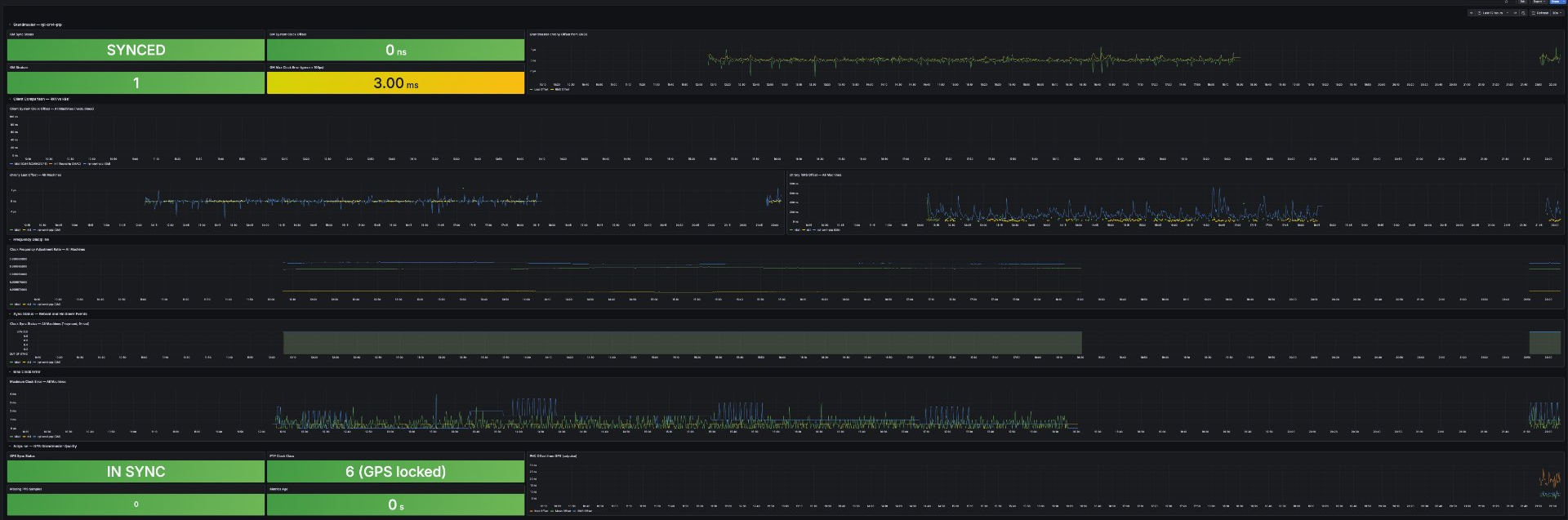
Grandmaster accuracy
When everything is working, SatPulse summaries look like this:
satpulsed: summary: absOffMax=18 absOffMean=6.4 offRMS=7.8 freqMean=3533 nMissing=0 nOutliers=0
The grandmaster PHC is within 18 nanoseconds of GPS truth, mean offset 6 nanoseconds.
Three-way timing comparison
With the grandmaster serving both PTP and NTP, the clients see all three tiers simultaneously.
| Source | Offset | Uncertainty |
|---|---|---|
| PTP, hardware timestamping | 3–4 ns | ±66–291 ns |
| LAN NTP, from this grandmaster | +31 to +108 µs | ±79–172 µs |
| WAN NTP, public pools | +1 to +3 ms | ±40–82 ms |
The grandmaster is the same physical machine serving all three. The difference is entirely in how time is delivered and measured. The +/- values are the uncertainty bounds reported by chrony: the range within which the true offset likely falls. PTP uses hardware timestamps in the PHY at the wire. LAN NTP uses software timestamps in the kernel, so it picks up jitter from kernel scheduling and interrupt handling. WAN NTP adds network path jitter on top of that.
Each tier is roughly 1000x worse than the one above it.
Client comparison: CM4 vs RK1
The CM4 client (k8s1) consistently achieves +/-66ns uncertainty. The RK1 achieves +/-291ns. Both are good results, but there is a 4x gap.
The CM4 client uses the same BCM54210PE PHY as the grandmaster. It timestamps at the PHY layer, right at the wire. The RK1 uses a Rockchip GMAC with a different PHC implementation. The timestamping happens at the MAC layer rather than the PHY layer, one step further from the wire. Every additional stage between the packet arriving at the silicon and the timestamp being captured adds jitter. The +/-291ns floor on the RK1 reflects that.
#* PTP   0   0   377   1    -3ns[  -4ns] +/-  291ns   <- RK1
#* PTP   0   0   252   2    +3ns[  +3ns] +/-   66ns   <- k8s1 (CM4)
Topology matters
The grandmaster plugged into a TP-Link AXE5400 consumer router vs directly into the Turing Pi switch.
Through the consumer router:
ptp4l: master offset    -16580 s2 path delay    469541
ptp4l: master offset   -178615 s2 path delay    485331
ptp4l: master offset    246261 s2 path delay    485331
Path delay around 480 microseconds, offsets swinging +/-700 microseconds.
Direct to the Turing Pi switch:
ptp4l: master offset        -13 s2 path delay      2615
ptp4l: master offset        127 s2 path delay      2607
ptp4l: master offset        -14 s2 path delay      2615
Path delay around 2.6 microseconds, offsets within +/-130 nanoseconds.
A 180x improvement in path delay just from removing the consumer router. Consumer routers buffer packets through software queues with variable and unpredictable delay. That variability goes directly into the PTP path delay calculation and degrades the offset estimate. The Turing Pi switch passes traffic at hardware speed with consistent delay.
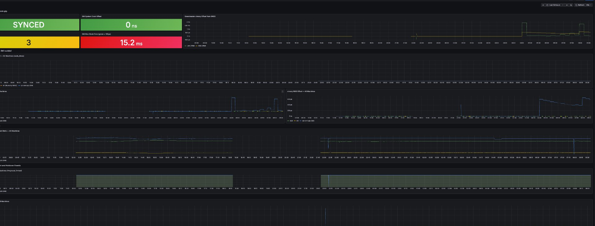
Holdover test
I disconnected the GPS antenna for 10 hours overnight. Without GPS input, SatPulse goes into holdover and the grandmaster runs on the CM4’s local crystal reference alone. clockClass changes from 6 (GPS locked) to 52 (holdover).
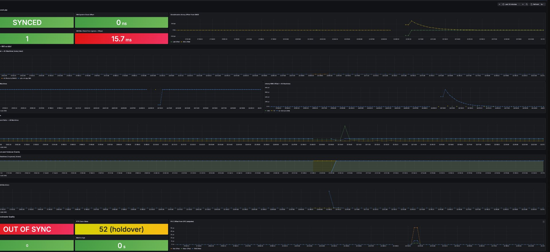
The GM clock drifted to a maximum error of around 15ms over 10 hours. The more interesting result was on the clients:
#* PTP   0   0   377   0   +4ns[  +26ns] +/-  291ns   <- RK1 after 10 hours holdover
#* PTP   0   0   110   4  -118ns[ -168ns] +/-  205ns   <- k8s1 after 10 hours holdover
Both clients stayed on PTP the entire time. Neither fell back to WAN NTP. The crystal reference held well enough that chrony never saw a reason to abandon the PTP source.
For my use case this is sufficient. If you need guaranteed holdover accuracy across extended outages or power loss, you need hardware with a TCXO or OCXO, none of which are present in this build.
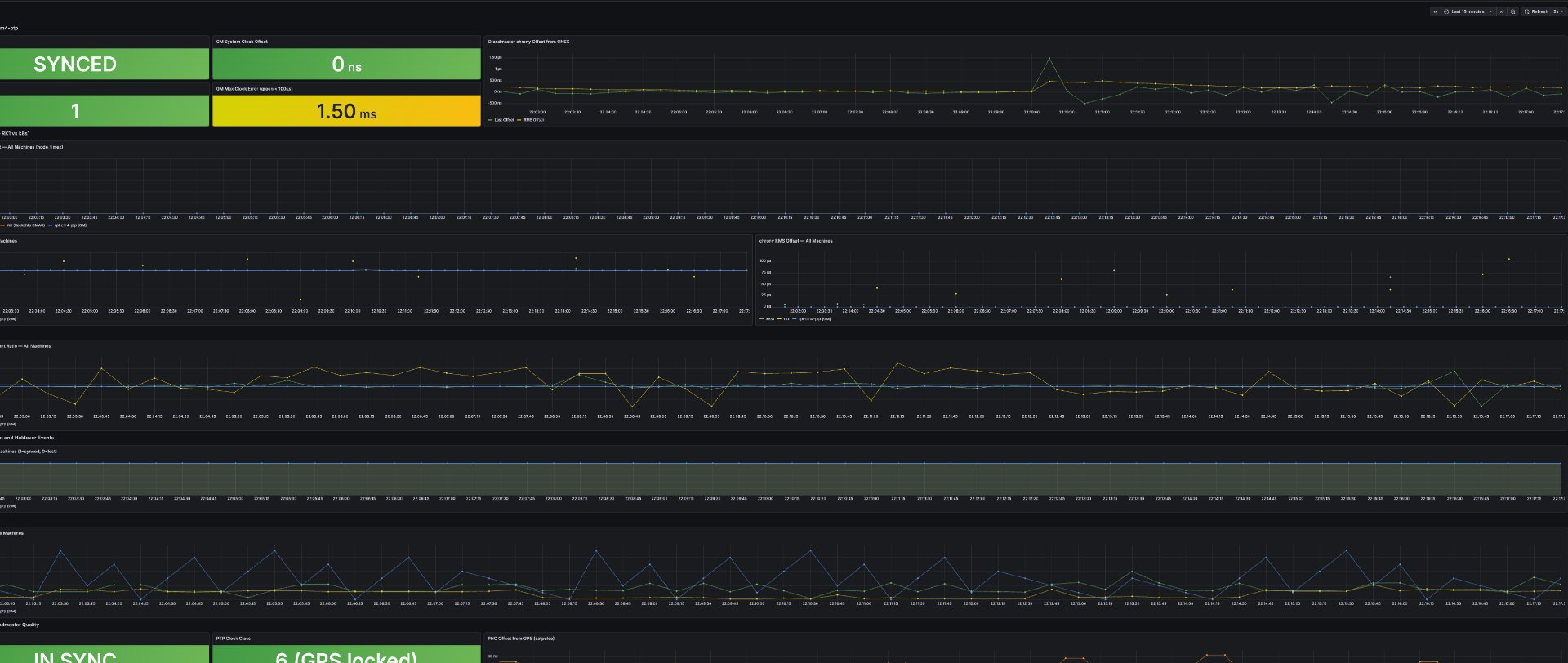
Monitoring
I set up Prometheus and Grafana to capture data from all three machines. The stack includes node_exporter and chrony_exporter on the grandmaster and both clients, plus a custom satpulse exporter on the grandmaster that parses journald output and exposes PHC offset, sync status, clockClass, and missing sample counts as Prometheus metrics.
Key metrics to watch:
satpulse_sync_status, 1=GPS locked, 0=holdoversatpulse_clock_class, 6=GPS locked, 52=holdoversatpulse_offset_max_nanoseconds, worst-case PHC offset from GPS in the last 30s windowchrony_tracking_last_offset_seconds, system clock offset from referencenode_timex_sync_status, kernel sync flag, drops to 0 during outages
Speed of light sanity check
Light travels approximately 30 centimeters per nanosecond.
The grandmaster PHC is within 7 nanoseconds of GPS truth on average. That is the time it takes light to travel about 2 meters.
The CM4 client system clock is within 3-10 nanoseconds of GPS truth. That is the time it takes light to travel across a small room.
The Build
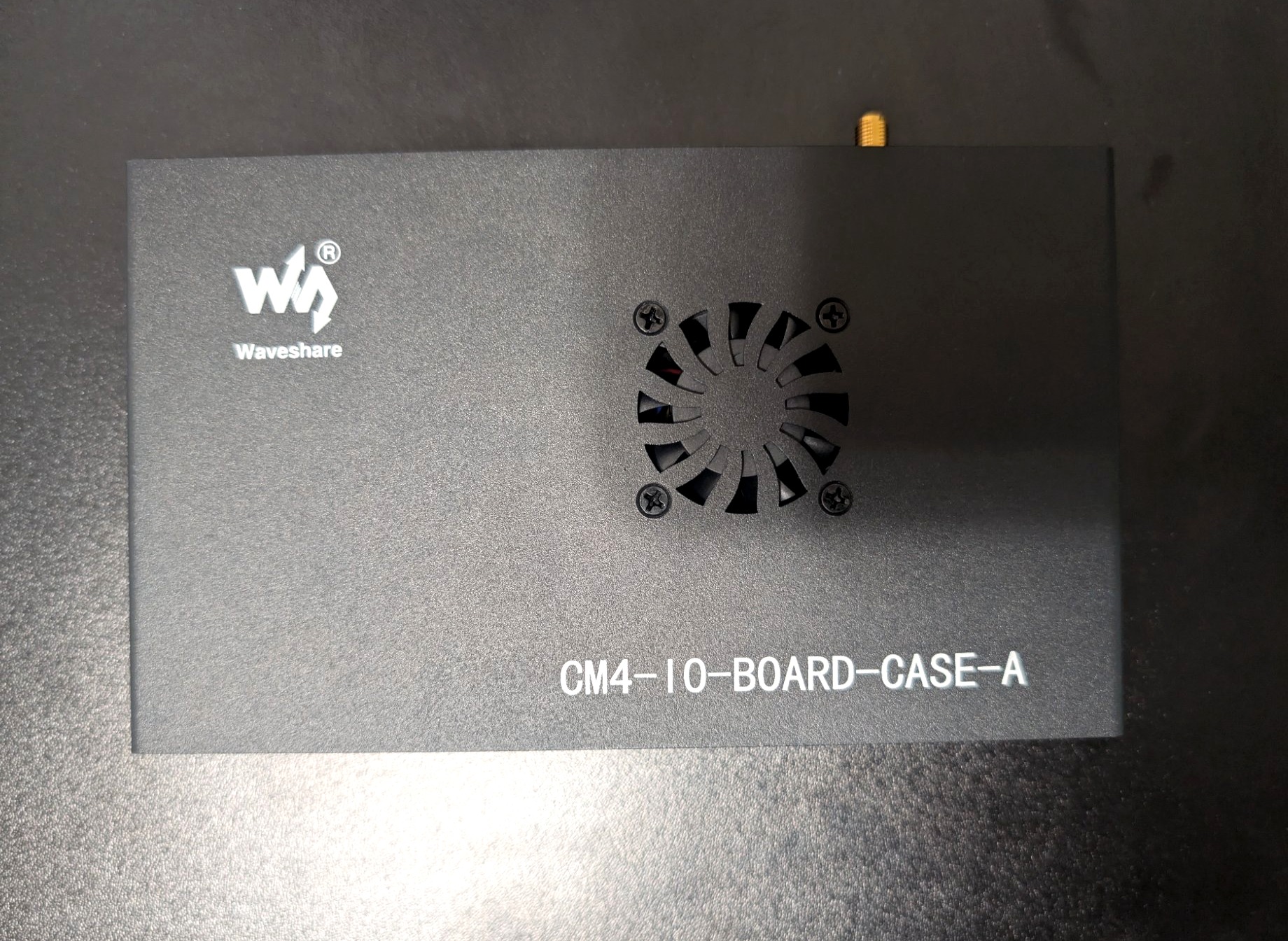
The finished grandmaster fits in a Waveshare CM4-IO-BOARD-CASE-A aluminum enclosure. The SMA antenna connector exits through the top panel. Five Dupont wires connect the SR1723U10 GPS module to the 40-pin header and J2 header inside.
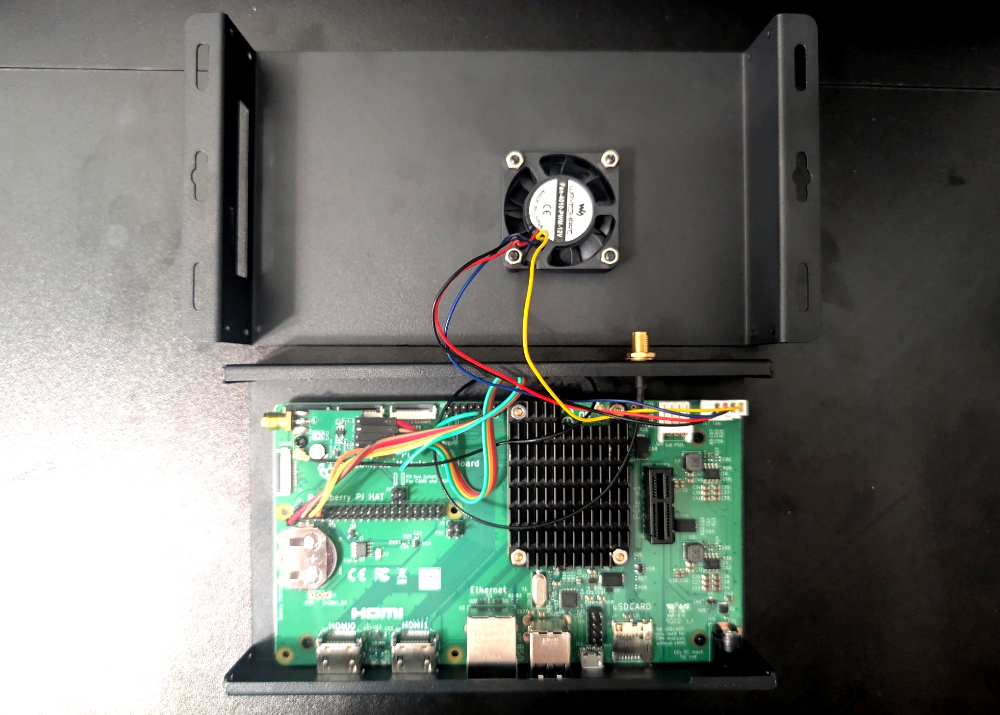
The case lid holds the fan and has a cutout for the SMA bulkhead connector. The Dupont wires run from the GPS module on the board up through the case to the J2 header.
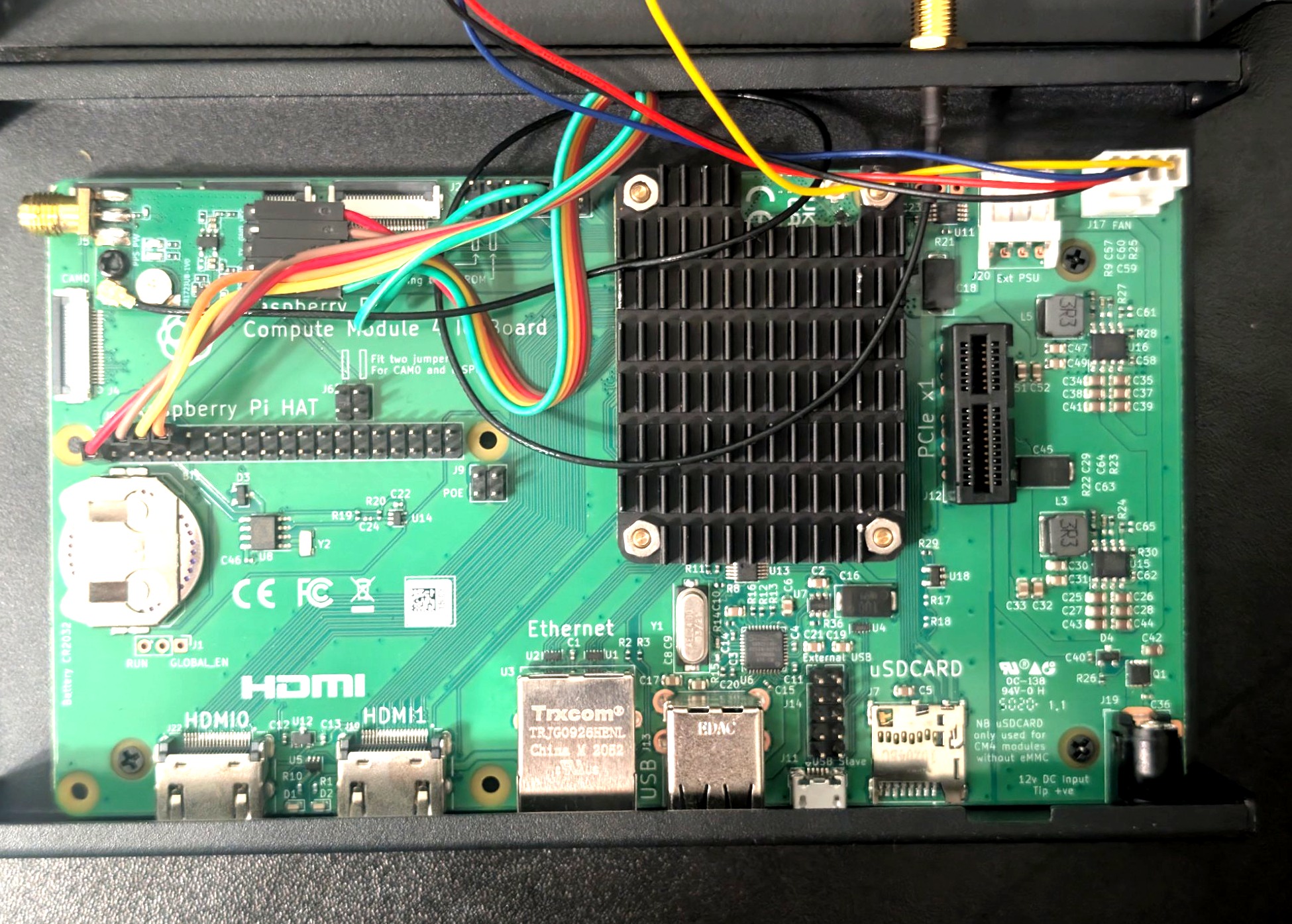
The GPS module sits near the 40-pin header on the upper left. The green wire carrying the PPS signal runs to the J2 header near the Ethernet jack. The PCF85063A RTC battery holder is visible on the lower left with a CR2032 installed.
The SMA bulkhead on the top panel connects to the Bingfu active GPS antenna via a JEFA Tech U.FL to SMA pigtail routed internally. The enclosure measures 160mm x 100mm x 40mm.
References
- jclark/rpi-cm4-ptp-guide, the guide this build is based on
- SatPulse, the daemon that makes this work
- SatPulse switch recommendations, FS IES3110 details
- Part 2: Stratum 1 PTP Grandmaster: NanoPi R5S-LTS + NEO-M8N (Part 2)